CNC (Computer Numerical Control) machines have transformed modern manufacturing by automating precision cutting, drilling, milling, and shaping processes that once required extensive manual labor. Whether you’re a machinist, an engineering student, or a business owner considering an investment in CNC technology, understanding the core components of a CNC machine is essential. This guide breaks down every major part of a CNC machine, explaining how each contributes to accuracy, efficiency, and overall performance.
What Is a CNC Machine?
A CNC machine is an automated tool that uses computer-programmed instructions to control the movement of machinery and tools. Instead of relying on a human operator to manually guide cutting tools, CNC systems execute precise digital commands generated from CAD (Computer-Aided Design) and CAM (Computer-Aided Manufacturing) software. This automation results in higher accuracy, repeatability, and production speed compared to traditional manual machining.
Why Understanding Its Components Matters
Knowing how each part of a CNC machine functions helps operators troubleshoot issues faster, maintain equipment properly, and choose the right machine for specific manufacturing needs. It also helps buyers evaluate machines based on performance rather than just price.
Core Structural Components
Machine Bed and Frame
The bed, or frame, is the foundational structure that supports all other components. It’s typically made from cast iron or heavy-duty steel to minimize vibration and maintain rigidity during high-speed operations. A stable frame is critical because even minor vibrations can compromise the accuracy of the finished part.
Worktable
The worktable holds the workpiece in place during machining. Depending on the machine type, it may move along one or more axes (X, Y, or Z) to position the material precisely under the cutting tool. Many worktables include T-slots or clamping systems to securely fasten workpieces of various shapes and sizes.
The Control System
CNC Controller
The CNC controller is essentially the “brain” of the machine. It interprets G-code and M-code instructions generated by CAM software and translates them into precise movements. Modern controllers often feature touchscreen interfaces, real-time diagnostics, and programmable logic for complex machining sequences.
Servo Motors and Drives
Servo motors convert electrical signals from the controller into mechanical motion, moving the machine’s axes with high precision. Drives regulate the power sent to these motors, ensuring smooth acceleration, deceleration, and positioning accuracy — all essential for maintaining tight tolerances.
Feedback Devices (Encoders)
Encoders monitor the exact position and speed of each axis in real time, sending this data back to the controller. This closed-loop feedback system allows the CNC machine to make instant corrections, ensuring the tool stays exactly on the programmed path.
Motion and Positioning Components
Ball Screws
Ball screws convert rotational motion from the servo motor into precise linear movement along the machine’s axes. Their design minimizes friction, allowing for smoother, more accurate positioning compared to traditional lead screws.
Linear Guides and Rails
Linear guides support and direct the movement of the worktable or spindle along a fixed path. High-quality guides reduce friction and wear, contributing to longer machine life and more consistent machining results.
Axes of Movement
Most CNC machines operate along multiple axes — commonly X, Y, and Z for basic three-axis machines, with more advanced models featuring four or five axes for complex geometries. Each additional axis increases the machine’s ability to produce intricate parts without repositioning the workpiece manually.
The Cutting System
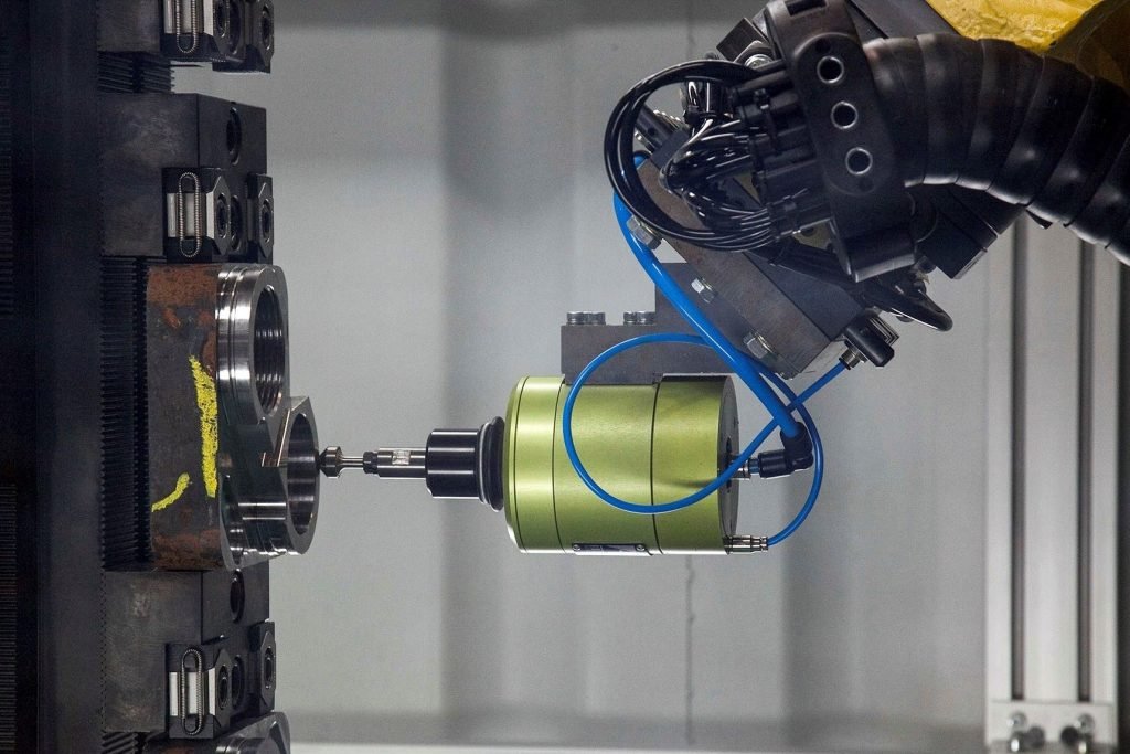
Spindle
The spindle holds and rotates the cutting tool at high speeds, directly influencing the machine’s cutting capability and surface finish quality. Spindle speed, measured in RPM (revolutions per minute), varies depending on the material being machined and the type of operation performed.
Tool Holder and Tool Changer
The tool holder secures the cutting tool within the spindle. Many CNC machines include an automatic tool changer (ATC), which allows the machine to switch between multiple tools during a single job without manual intervention — significantly reducing downtime and increasing productivity.
Cutting Tools
Cutting tools come in various forms, including end mills, drills, and taps, each designed for specific machining operations such as milling, drilling, or threading. Tool material — such as carbide or high-speed steel — affects durability and performance depending on the workpiece material.
Support Systems
Coolant System
During machining, friction generates significant heat that can damage both the tool and the workpiece. The coolant system delivers cutting fluid to the tool-workpiece interface, reducing heat buildup, flushing away chips, and extending tool life.
Chip Conveyor
As material is cut away, metal or plastic chips accumulate around the worktable. A chip conveyor automatically removes this debris, keeping the machining area clean and preventing chip buildup from interfering with precision cutting.
Enclosure and Safety Guards
Modern CNC machines are typically enclosed with safety guards to protect operators from flying debris, coolant splashes, and moving parts. These enclosures also help contain noise and improve workplace safety compliance.
Power and Electrical Components
Power Supply Unit
The power supply unit converts incoming electrical power into the appropriate voltage and current needed to run the machine’s motors, controller, and auxiliary systems reliably.
Electrical Cabinet
Housing the machine’s wiring, relays, circuit breakers, and control components, the electrical cabinet protects sensitive electronics from dust, coolant, and debris generated during machining operations.
Software Integration
CAD/CAM Software
While not a physical component, CAD/CAM software plays a vital role in the CNC machining process. CAD software is used to design the part, while CAM software converts that design into machine-readable G-code instructions that guide the CNC machine’s movements.
Human-Machine Interface (HMI)
The HMI, often a touchscreen or control panel, allows operators to input commands, monitor machining progress, and adjust settings in real time. A well-designed HMI improves usability and reduces the learning curve for new operators.
How These Components Work Together
Every component of a CNC machine plays an interconnected role. The controller sends instructions to the servo motors, which move the axes via ball screws and linear guides. The spindle rotates the cutting tool, shaping the workpiece secured on the worktable, while the coolant system and chip conveyor maintain a clean, efficient cutting environment. This seamless coordination between mechanical, electrical, and software systems is what makes CNC machining so precise and reliable.
Final Thoughts
Understanding the main components of a CNC machine — from the structural frame to the intricate control systems — provides valuable insight into how these powerful machines achieve such remarkable precision. Whether you’re troubleshooting a machining issue, training new operators, or evaluating equipment for purchase, knowing how each part contributes to the overall process is key to maximizing performance, minimizing downtime, and producing high-quality parts consistently.
One Response