CNC Machine Architecture: Complete System Overview
CNC (Computer Numerical Control) machines are among the most sophisticated tools in modern manufacturing, combining mechanical engineering, electronics, and software into a single automated system. Understanding CNC machine architecture — how its subsystems are structured and interact — is essential for engineers, machinists, and business owners looking to optimize performance, troubleshoot issues, or invest in new equipment. This article provides a complete overview of CNC machine architecture, breaking down each layer of the system and how it contributes to precision manufacturing.
What Is CNC Machine Architecture?
CNC machine architecture refers to the overall design and organization of a CNC system’s mechanical, electrical, and software components. Rather than functioning as isolated parts, these elements are engineered to work together in a tightly coordinated loop — receiving digital instructions, converting them into physical motion, and continuously verifying accuracy through feedback systems.
Why Architecture Matters in CNC Systems
The architecture of a CNC machinedirectly affects its precision, speed, reliability, and flexibility. A well-designed architecture minimizes errors, reduces downtime, and allows manufacturers to produce complex parts with tight tolerances. Poorly integrated systems, on the other hand, can lead to inaccuracies, frequent breakdowns, and costly production delays.
The Three Core Layers of CNC Architecture
CNC machine architecture is generally organized into three interconnected layers: the mechanical layer, the control layer, and the software layer. Each layer plays a distinct role while remaining dependent on the others for smooth operation.
1. Mechanical Layer
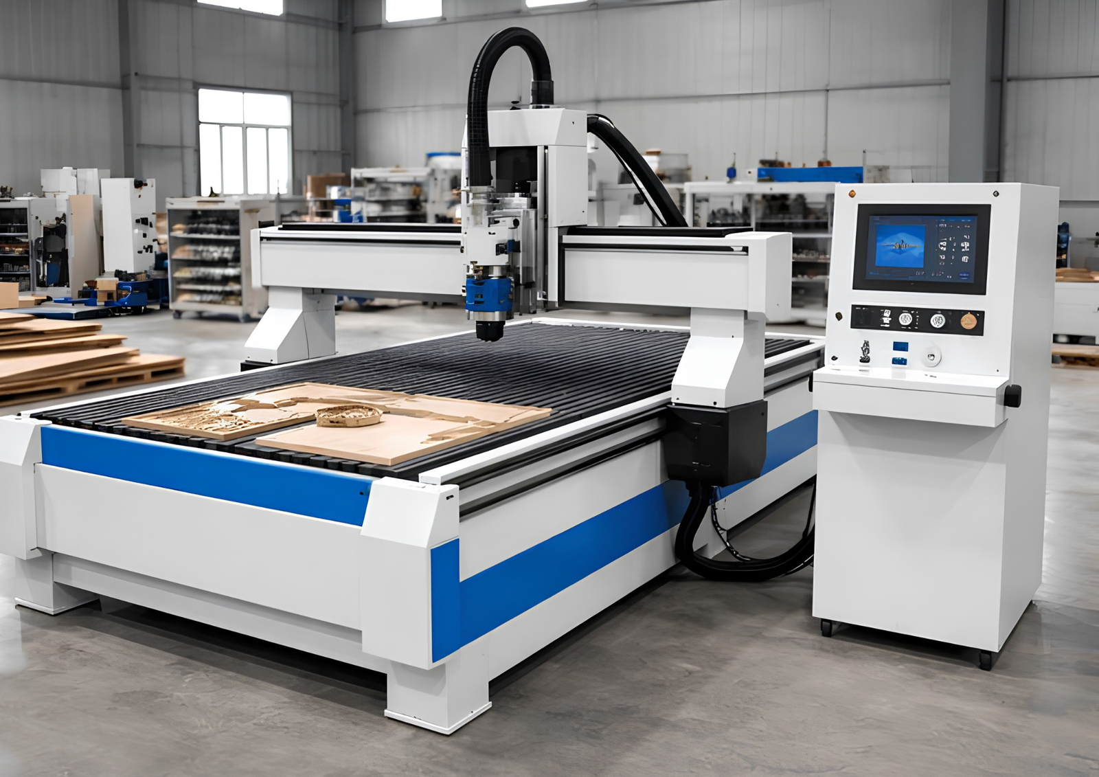
This layer includes all physical components responsible for movement and material shaping, such as the machine frame, worktable, spindle, and axes.
2. Control Layer
The control layer manages the electrical and computational systems that direct the mechanical layer, including the CNC controller, servo drives, and feedback sensors.
3. Software Layer
This layer encompasses the programming and digital instructions — including CAD/CAM software and G-code — that define what the machine produces and how.
Mechanical Architecture: The Physical Foundation
Machine Frame and Base
The frame provides structural rigidity, absorbing vibrations and maintaining alignment during high-speed operations. Most industrial CNC machines use cast iron or welded steel frames designed to resist thermal expansion and mechanical stress.
Axis Configuration
CNC machines are classified by the number of axes they operate on. Basic models use three axes (X, Y, Z), while advanced multi-axis machines add rotational movement (A, B, or C axes) for machining complex, multi-sided parts without repositioning the workpiece.
Spindle Assembly
The spindle assembly houses the rotating shaft that holds and drives the cutting tool. Spindle architecture varies based on application — high-speed spindles are used for fine detail work, while high-torque spindles handle heavy material removal.
Motion Transmission Components
Ball screws, linear guides, and rack-and-pinion systems convert rotational motor movement into precise linear motion. The choice of transmission system affects speed, load capacity, and positioning accuracy.
Control Architecture: The Command Center
CNC Controller
The CNC controller serves as the central processing unit of the entire system. It interprets programmed instructions, coordinates motor movements, and manages real-time adjustments to maintain accuracy throughout the machining process.
Servo and Stepper Motor Systems
Servo motors offer closed-loop control with continuous feedback, making them ideal for high-precision applications. Stepper motors, while generally less expensive, operate on an open-loop system and are often used in lighter-duty CNC machines.
Drive Systems
Drives regulate the electrical power delivered to motors, controlling speed, torque, and directional changes. Properly matched drive systems ensure smooth acceleration and deceleration, reducing mechanical strain.
Feedback and Sensor Systems
Encoders and other sensors continuously monitor axis position, speed, and tool status. This feedback loop allows the controller to make micro-adjustments in real time, ensuring the machine stays within programmed tolerances.
Software Architecture: The Digital Blueprint
CAD Software
Computer-Aided Design (CAD) software allows engineers to create detailed 2D or 3D models of the part to be manufactured. These digital designs form the foundation for all subsequent machining instructions.
CAM Software
Computer-Aided Manufacturing (CAM) software converts CAD models into machine-readable instructions, generating toolpaths, cutting sequences, and speed settings tailored to the specific CNC machine and material.
G-Code and M-Code Programming
G-code controls movement instructions such as positioning, speed, and cutting paths, while M-code manages auxiliary functions like coolant activation, spindle start/stop, and tool changes. Together, these codes form the language that bridges software design and physical machining.
Human-Machine Interface (HMI)
The HMI allows operators to interact directly with the CNC system, offering real-time monitoring, manual overrides, and diagnostic tools. A well-designed HMI improves operational efficiency and reduces the likelihood of programming errors.
Auxiliary Systems Supporting CNC Architecture
Automatic Tool Changer (ATC)
Many CNC machines integrate automatic tool changers, allowing rapid switching between multiple cutting tools during a single operation. This reduces manual intervention and significantly shortens production cycles.
Coolant and Lubrication Systems
These systems manage heat and friction generated during machining, protecting both the cutting tool and workpiece from thermal damage while also extending equipment lifespan.
Chip and Debris Management
Chip conveyors and vacuum systems remove machining debris from the work area, maintaining a clean environment that supports consistent precision and reduces the risk of equipment jams.
Enclosures and Safety Systems
Modern CNC architecture includes safety enclosures, emergency stop mechanisms, and interlocks designed to protect operators from moving parts, flying debris, and coolant exposure.
How CNC Architecture Enables Precision Manufacturing
The strength of CNC machine architecture lies in its closed-loop design. Instructions generated through CAD/CAM software are translated into G-code, which the controller interprets to direct servo motors and drives. As the machine moves, feedback sensors continuously report position and speed data back to the controller, allowing instant corrections. This constant cycle of command, execution, and verification is what allows CNC machines to achieve tolerances measured in fractions of a millimeter.
Choosing CNC Architecture for Specific Applications
Prototyping and Small-Batch Production
For prototyping, flexible architecture with quick tool-change capabilities and multi-axis functionality is often prioritized to accommodate frequent design changes.
High-Volume Manufacturing
In high-volume settings, architecture emphasizing speed, automation, and minimal downtime — such as advanced ATC systems and robust drive systems — is critical for maintaining production efficiency.
Complex Geometries
Multi-axis architecture, particularly five-axis systems, is essential for manufacturing parts with intricate curves, undercuts, or angled features that would otherwise require multiple setups.
Final Thoughts
CNC machine architecture represents a carefully engineered integration of mechanical structure, electronic control, and digital programming. Each layer — from the rigid machine frame to the precise feedback loops of the control system and the intelligent instructions generated by CAD/CAM software — plays an essential role in achieving the speed, accuracy, and reliability that define modern CNC manufacturing. Understanding this architecture not only helps operators and engineers troubleshoot and optimize performance but also empowers manufacturers to select the right CNC systems for their specific production needs.
One Response